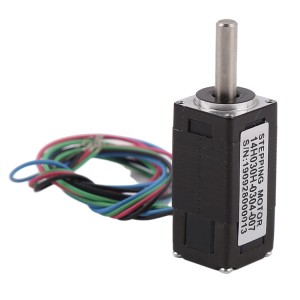
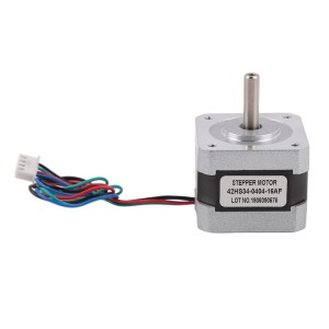
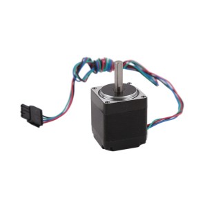
Motora gavavêtinê ya hîbrîd a xêzikî NEMA8 20 mm bi şafta pêça pêşeng a dimeşe
Terîf
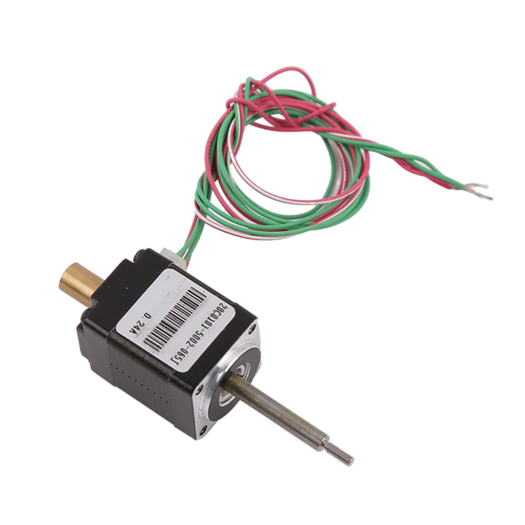
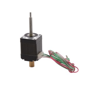
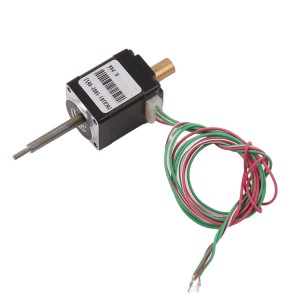
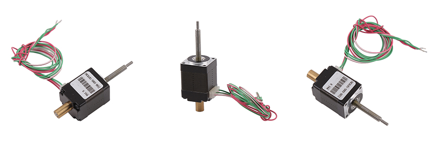
Ev motora gavavêtinê ya hîbrîd NEMA8 (mezinahiya 20 mm) e ku xwedan şaftek direve, ku wekî şafta ne-dîlgirtî tê zanîn.
Ne mîna motora gavavêtinê ya bi şafta gilover/şafta D, ev şafta direve dema ku di heman demê de dizivire azad e ku ber bi jor û jêr ve biçe.
Ev wekî motora gavavêtina xêzik tê zanîn, ku dikare tevgera xêzik bike.
Leza tevgera xêzikî bi frekansa ajotinê û pêşenga pêça pêşeng ve tê destnîşankirin.
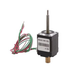
Li pişta motorê gwîzek destî heye, ku dikare were bikar anîn da ku motorê dema ku elektrîk qut dibe bi destan bizivirîne, an jî dikare bi kodkeran re ji bo pergala çerxa nêzîk were civandin.
Parametre
| Jimareya Modelê | 20C0101 |
| Dirêjahiya motorê | 20mm (NEMA8) |
| Voltaja ajotinê | 5V DC |
| Berxwedana pêlavê | 20.8Ω ± 10%/qonax |
| Hejmara qonaxan | 2 qonax |
| Goşeya gavê | 1.8°/gav |
| Rêjeya herikînê | 0.24A/qonax |
| Kêmtirîn kişandin (300PPS) | 2.4KG |
| Dirêjahiya gavê | 0.0015mm/gav |
Nexşeya Sêwiranê
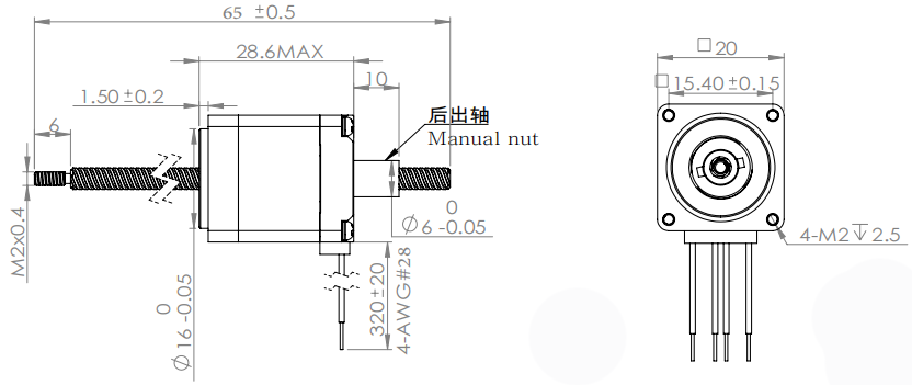
Derbarê pêça pêşeng
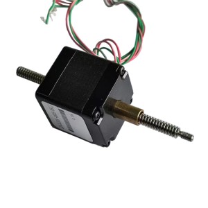
Vîza pêşeng a ku li ser motora gavavêtinê ya hîbrîd a xêzik tê bikar anîn, bi gelemperî vîza pêşeng a trapezoidal e.
Mînakî ji bo pêça pêşeng a Tr3.5*P0.3*1N.
Tr tê wateya cureyê pêça pêşeng a trapezoidal
P0.3 tê vê wateyê ku pîça pêça pêşeng 0.3 mm e
1N tê vê wateyê ku ew vîça pêşengiya yek-destpêkê ye.
Pêşkêşkirina pêça rêber = hejmara destpêkê * pitch
Ji bo vê pêça pêşeng a taybetî, pêşengiya wê 0.3 mm ye.
Goşeya gavavêtina motorê ya motora gavavêtina hîbrîd 1.8 pile/gav e, ku ji bo zivirandina yek zivirînê 200 gavan digire.
Dirêjahiya gavê tevgera xêzikî ye ku motor çêdike, dema ku ew gavekê diavêje.
Ji bo pêçek pêşeng a 0.3 mm, dirêjahiya gavê 0.3 mm / 200 gav = 0.0015 mm / gav e.
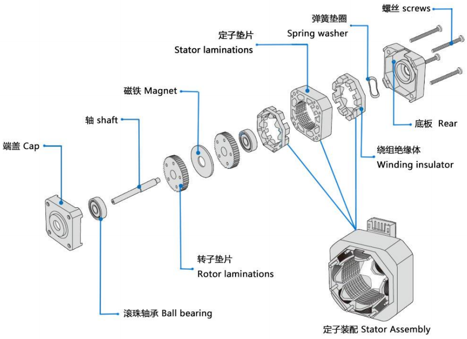
Struktura bingehîn a motorên gavê yên NEMA
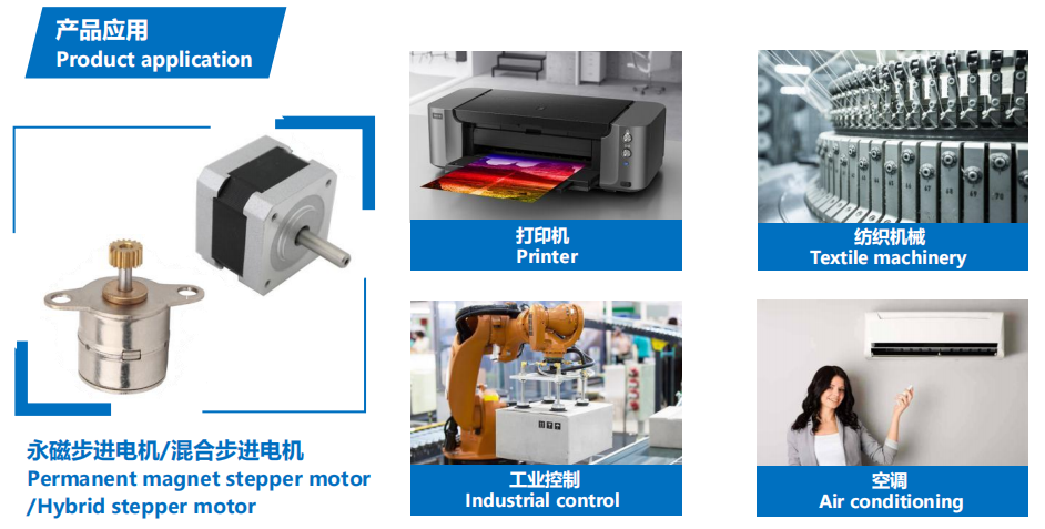
Serlêdana motora gavê ya hîbrîd
Ji ber çareseriya bilind a motorên gavavêtinê yên hîbrîd (200 an 400 gav di her zivirînê de), ew bi berfirehî ji bo sepanên ku hewceyê rastbûnek bilind in, wekî:
Çapkirina 3D
Kontrola pîşesaziyê (CNC, makîneya frezkirina otomatîk, makîneyên tekstîlê)
Amûrên pêvekirî yên komputerê
Makîneya pakkirinê
Û pergalên din ên otomatîk ên ku hewceyê kontrola rastbûna bilind in.
Divê xerîdar prensîba "pêşî motorên gavavêtinê hilbijêrin, dûv re ajokar li gorî motora gavavêtinê ya heyî hilbijêrin" bişopînin.
Çêtir e ku moda ajotina gav-tav ji bo ajotina motorek gavavêtinê ya hîbrîd bikar neynin, û lerzîn di bin ajotina gav-tav de mezintir e.
Motora gavavêtinê ya hîbrîd ji bo rewşên bi leza kêm guncawtir e. Em pêşniyar dikin ku leza ji 1000 rpm (6666PPS li 0.9 pileyan) derbas nebe, bi tercîhî di navbera 1000-3000PPS (0.9 pileyan) de be, û ew dikare bi qutiyek gearê ve were girêdan da ku leza xwe kêm bike. Motor di frekanseke guncaw de xwedî karîgeriya xebatê ya bilind û dengek kêm e.
Ji ber sedemên dîrokî, tenê motorên bi voltaja nominal a 12V 12V bikar tînin. Voltaja din a binavkirî ya li ser nexşeya sêwiranê ne tam voltaja ajotinê ya herî guncaw ji bo motorê ye. Xerîdar divê li gorî hewcedariyên xwe voltaja ajotinê ya guncaw û ajokera guncaw hilbijêrin.
Dema ku motor bi leza bilind an barekî mezin tê bikaranîn, bi gelemperî ew rasterast bi leza xebatê dest pê nake. Em pêşniyar dikin ku frekans û leza hêdî hêdî zêde bikin. Ji ber du sedeman: Ya yekem, motor gavan winda nake, û ya duyemîn, ew dikare deng kêm bike û rastbûna pozîsyonê baştir bike.
Divê motor di qada lerzînê de (di bin 600 PPS de) nexebite. Ger divê bi leza kêm were bikar anîn, pirsgirêka lerzînê dikare bi guhertina voltaja, herikînê, an jî zêdekirina hin nermkirinê were kêmkirin.
Dema ku motor di bin 600PPS (0.9 pile) de dixebite, divê ew bi herikîna piçûk, înduktansa mezin û voltaja nizm were ajotin.
Ji bo barên bi kêşeya inertiya mezin, divê motorek mezin were hilbijartin.
Dema ku rastbûnek bilindtir hewce be, ew dikare bi zêdekirina qutiya gerokê, zêdekirina leza motorê, an jî bi karanîna ajotina dabeşkirinê were çareser kirin. Her weha motorek 5-qonaxî (motora yekqutbî) dikare were bikar anîn, lê bihayê tevahiya pergalê nisbeten biha ye, ji ber vê yekê ew kêm kêm tê bikar anîn.
Mezinahiya motora Stepper:
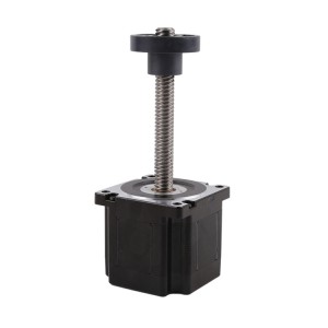
Niha motorên gavavêtinê yên hîbrîd ên me 20mm(NEMA8), 28mm(NEMA11), 35mm(NEMA14), 42mm(NEMA17), 57mm(NEMA23), 86mm(NEMA34) hene. Dema ku hûn motorek gavavêtinê ya hîbrîd hildibijêrin, em pêşniyar dikin ku hûn pêşî mezinahiya motorê diyar bikin, dûv re parametreyên din piştrast bikin.
Xizmeta xwerûkirinê
Sêwirana motorê dikare li gorî hewcedariya xerîdar were sererast kirin, di nav de:
Qûtra motorê: me motorên bi qûtra 6mm, 8mm, 10mm, 15mm û 20 mm hene
Berxwedana bobînê / voltaja nominal: berxwedana bobînê verastbar e, û bi berxwedana bilindtir, voltaja nominal a motorê bilindtir e.
Sêwirana braketê / dirêjahiya pêça pêşeng: heke xerîdar bixwaze braket dirêjtir/kurt be, bi sêwirana taybetî wekî kunên montajê, ew verastbar e.
PCB + kabloyên + pêvek: Sêwirana PCB, dirêjahiya kabloyê û pileya pêvekê hemî verastbar in, heke xerîdar hewce bike ew dikarin werin guhertin bo FPC.
Dema pêkhatinê
Ger nimûneyên me di stokê de hebin, em dikarin di nav 3 rojan de nimûneyan bişînin.
Heke nimûneyên me di stokê de tune bin, divê em wan hilberînin, dema hilberînê nêzîkî 20 rojên salnameyê ye.
Ji bo hilberîna girseyî, dema pêşengiyê bi mîqdara fermanê ve girêdayî ye.
Rêbaza dayinê û şertên dayinê
Ji bo nimûneyan, bi gelemperî em Paypal an Alibaba qebûl dikin.
Ji bo hilberîna girseyî, em dravdana T/T qebûl dikin.
Ji bo nimûneyan, em berî hilberînê dravdana tevahî berhev dikin.
Ji bo hilberîna girseyî, em dikarin berî hilberînê 50% pêş-dravdanê qebûl bikin, û 50% dravdana mayî berî barkirinê berhev bikin.
Piştî ku em ji 6 caran zêdetir fermanê bidin hevkariyê, em dikarin şertên din ên dravdanê yên wekî A/S (piştî dîtinê) danûstandinan bikin.
Pirsên Pir tên Pirsîn
1. Dema radestkirina nimûneyan bi gelemperî çiqas dirêj e? Dema radestkirina fermanên mezin ên paşîn çiqas dirêj e?
Demjimêra pêşengiya fermana nimûneyê nêzîkî 15 rojan e, dema pêşengiya fermana mîqdara girseyî 25-30 roj e.
2. Ma hûn xizmetên taybet qebûl dikin?
Em hilberên ku têne çêkirin qebûl dikin. Tevî parametreya motorê, celebê têla pêşeng, şafta derve û hwd.
3. Gelo mimkun e ku kodkerek li vê motorê were zêdekirin?
Ji bo vê celeb motorê, em dikarin kodkerê li ser qapaxa aşînkirina motorê zêde bikin.

